The timber section size is often determined by the strength of the section remaining after drilling holes for bolts or dowels or by the spacing requirements for the fasteners rather than the load-carrying capacity of the timber. Then provide nominal nailing or bolting pattern on the lap between these two designed connections.

Steel Beam Angles Moment Connection To Shs Column Detail Steel Beams Beams Steel
If the connectors prevent shrinkage splitting of the timber may occur.

. Figure 1 shows how the timber may split when movement is prevented. Design a bolted flange-plated FR moment connection between a W1850 beam and a W1499. CM 1 Ct 1 CL 1 CF.
Determine allowable stresses Fb 875 psi Fv 135 psi Determine factors. The embedding strength of the timber or wood. Connection strength mainly depends on connector and timber dimensions and load-.
Detailing a moment-resisting connection. The most commonly used moment resisting connections are bolted end plate beam-to-column connections. Also important in design is the concept of connections acting together.
2The embedding strength of the timber or wood-based material. Beam to column connection ti. Example of a bolted beam-column connection with slotted-in steel plate A commonly used beam-to-column wood-steel- wood bolted connection was considered in the study see Figure 1.
Horizontal timber member is connected to a vertical timber or steel member. Fully-Restrained FR Moment Connections The design of fully restrained FR moment connections is covered in Part 11 of the AISC Steel Construction Manual. A few principles of connection design d i Keep the load path as direct as possible Connect the loaded fibres Avoid tension perpendicular to grain stresses Make use of compression load transfer as much as possible Use steel elements when.
That methodology of the connection the elements made from glulam was used in the studies 2. Shear-plate connectors Shear-plate connector units consist of one shear-plate with a bolt washers and nut. A detailed design example WS TDG 33 Quick-connect Moment Connection 11-20pdf 224 MB EXPAN Timber Rivet Connection Efficient connection can be achieved by decreasing the difference between the capacity of wood and rivets.
Plan view of the connection. 3The withdrawal strength of the dowel 71 Member notation Member thickness t 1and t 2. Be able to recommend fastening guidelines for wood to steel wood to concrete and wood to wood connections.
Modelling the connection As a steel beam is inserted in the glulam member this is effectively a double-shear steel-to-timber connection. IIB-2 Example IIB-1 Bolted Flange-Plate FR Moment Connection beam-to-column flange Given. Nails screws Nails screws and bolts can be used together in a.
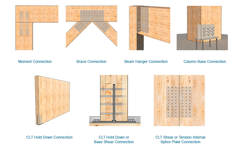
The application of moment-resisting connections in timber structures offers designers the potential to make the structural system as efficient as possible. Moment Resisting Timber Connections Moment connection types Beam splice Beam to column connection Corner connection A few principles of connection design Keep the load path as direct as possible Connect the loaded fibres Avoid tension perpendicular to grain stresses Make use of compression load transfer as much as possible Use steel elements. Considering an unreinforced joist-to-column connection with slotted-in steel plates as baseline an increase in capacity by a factor of 17 was observed when the connections were reinforced.
Design a bolted flange-plated FR moment connection between a W1850 beam and a W1499. Cfu 1 Ci 1 Cr 1 University of Michigan TCAUP Structures II Slide 21 of 52 Adjustment Factors Allowable Flexure Stress Fb. Steel-to-timber connections and in demountable timber-to-timber joints.
The three main parameters which influence the load-carrying capacity behaviour of joints with dowel-type fasteners are. Timber Rivet Connection explains the timber rivet connection optimised for the use of structural seasoned wood products. Each glulam side has a width b 1 72 m m.
1The bending capacity of the dowel or yield moment. Then design the lap connection for the moment using a force couple one force near the bearing wall and one force near the end of the lap. If the cantilever moment needs to be balanced review the effect of the backing beam moment connection.
A total of 30 connection tests were conducted under monotonic M series and reverse cyclic loading C series. Selected modern moment resisting timber connections Classic solutions Classic solution of the connection transmitting bending moment consists of shaping the geometry of the node to provide the transfer of the unusual load by conventional fasteners. Bolts coach screws and timber connectors split-rings and shear-plates all have higher capacities than nails and screws making them better suited to applications where a large load is imposed and there is limited space for fasteners.
Commonly these are used in conjunction with proprietary and custom designed metal. This is 150 mm minus 6 mm plate thickness divided by 2 for each side Figure 2. Moment Resisting Timber Connections.
Connections are an essential part of any structure and in timber structures they are often the most critical part of a design. Be familiar with Technical Report 12 and provisions for connection design beyond NDS requirements. These are shown in the figure below.
The bending capacity of the dowel or yield moment. The moment in the web 0158 445 7031 kNm The shear force in the web 157 kN The axial force in the web 0398 41 16318 kN Choice of Bolt Number and Configuration Resistances of Bolts The shear resistance of bolts at ultimate limit state For M24 bolts in single shear 132 kN For M24 bolts in double shear 265 kN Flange Splice. Be familiar with current wood member connection solutions and applicable design requirements.
This paper evaluates the performance of moment-resisting bolted timber connections with self-tapping wood screws acting as perpendicular-to-grain reinforcement. Maximum Concentrated Load a Box Beam Can Carry. DESIGN EXAMPLES Comparative Shrinkage of Sawn Timber and Glulam Beams 499 Simple Beam Design 500 Upside-Down Beam Analysis 502 Tension-face Notch 504 Compression-face Notch 505 Sloped End Cut 507 Beam Stability Effective Length Method 509 Beam Stability Equivalent Moment Method 512 Cantilever Beam Stability Equivalent Moment.
This type of splitting often occurs when treated timber which generally still has a high moisture content is bolted to uprights. Eurocode 5 section 89 explains the connection design method for split-rings. Full depth end plate Extended end plate Stiffened extended end plate Haunched beam Instead of bolted beam-to-column connections welded connections can be used.
Hybrid Timber Frame Connection Detail Timber Frame Hq Timber Frame Timber Frames On Wall
Designing With Internal Knife Plates Mass Timber Connections Mtc Solutions

Ec Steel And Timber Design In Scia Engineer 15
2

Esdep Lecture Note Wg11 Construction Details Architecture Architectural Section Train Station Architecture

Timber Roof With Clay Tiles Ridge Connection Detail Timber Roof Clay Tiles Timber
2

Moment Resisting Timber Connections Ppt Video Online Download
0 comments
Post a Comment